Machine-level Programming
The first programmers used binary codes to create instructions for the computers which was a tedious task and it was far from how humans think. The idea of experimenting with the art of writing programs in machine codes has been forming at the back of my mind for quite a while, so I decided to scratch the itch and experiment with a tiny code sample written in machine language.
I chose RISC-V instruction set in its RV32I format and a bare-metal platform for the experiment, but the principles are similar for other architectures and platforms. I am targeting bare-metal SiFive Freedom E300 platform which is supported in QEMU. This platform has on-chip volatile memory starting from 0x8000_0000 address and I will use this memory address as a base address for the 32 bit counter in the program. The program will be put in an assembly source file and processed with a standard GCC tool chain to get the final binary image. Another option could be preparing a binary image fully manually, but I find it unnecessarily complicated and less expressive for a simple experiment. I will also use QEMU for testing the program.
Example
An example program will be a trivial counter incrementing its value in an indefinite loop. The program will have only four steps:
- load a value from memory to a register
- increment the value in the register
- store new value to the same location in memory
- jump back to the first step
Encoding each of these steps into machine instructions requires the following:
-
Determining instruction format
RISC-V architecture defines six different core instruction formats12 and they all have distinct fields and operand positions to accommodate certain type of instructions. Each assembly instruction generated by compiler or written by programmer corresponds to one of these formats.
-
Encode an instruction with its operands into a machine word
Put opcode and operands into their corresponding bit fields in the instruction word.
-
Add machine word to assembly program file
Add instruction words to the .text section of the assembly program.
Let’s start converting our pseudo-program into binary digits.
Load counter from memory
RV32I is a load-store architecture which means that most instructions operate on registers and only load and store instructions access memory. As the program modifies a single value, one register is reserved for its memory address. Load and store instructions will use this register as a source of base memory address. So the first instruction in the program should preload the base memory address to the register for further use. I will use x10 register for this purpose. Load upper intermediate (LUI) instruction can be used to build a 32-bit constants in a register. This is a U format instruction. Here is how it is formed:
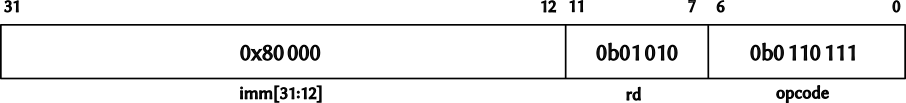
The first 7 bits of any instruction are reserved for the opcode. In case of LUI instruction the opcode is 0b0110111. You can find all opcodes in the RISC-V instruction set manual2.
The next field in the instruction is the operation destination register. It contains the number of the register where the result of the operation is placed. This field is 5 bits in size which is enough to address all 32 registers. As I am using the x10 register, this field has 0b01010 value or 10 in decimal format.
The last field in the instruction contains an immediate value which is placed into the destination register rd. The instruction has only 20 bits left for the immediate value, so bits from 12 to 31 are loaded into the destination register and the lowest 12 bits are filled with zeros. If these lowest bits contain non-zero values then they should be added with another instruction to form the required value. It is not needed to add these lower 12 bits in my case as the counter is located at address 0x8000_0000.
Combined instruction in hexadecimal format is 0x80000537 and this is the first instruction in the program.
The second instruction is used to actually load the counter value from the memory location to a register. I am going to use x11 register to store the counter value. Loading data from memory is an I format instruction and it has the following structure:
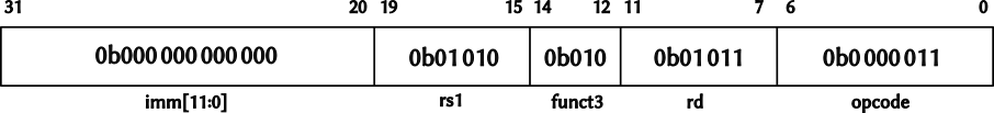
Let’s break down this instruction into its components. The opcode field is at the same place as in the previous instruction and its value 0b0000011 can be found in the RISC-V instruction set manual. rd field specifies the destination register which is x11, so the value of this filed is 0b01011. Next goes 3 bits wide funct3 field which in case of load instructions describes data type to be loaded from memory. In this case it is word and the value of this field should be 0b010.
The last two fields are used combined to form the memory address for the loading operation. rs1 is the register number containing base address value which is the upper 20 bits and imm[11:0] field contains an offset from the base address. The offset is sign-extended value, so it can be used to offset the base address in both directions in address space. I already prepared the base address in the x10 register, so the value 0b01010 of the rs1 field corresponds to the number of this register. As I don’t need any offset from the base address stored in the x10, the value of the imm[11:0] field should be 0b000000000000. Having all fields of the instruction ready, the final value of the second instruction in hexadecimal representation is 0x00052583.
Increment counter
Next step in the program is to increment the counter value stored in the register and I am going to use integer register-immediate instruction for this operation. This is another I format instruction, but this time it has different operands:
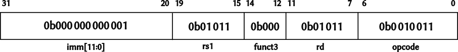
The opcode for adding a sign-extended immediate value to a register is 0b0010011. The source and destination registers are the same to store the resulting counter value in the same register. As the counter already loaded into the x11 register, the rd and rs1 fields contain 0b01011 value. The funct3 field is used to further describe the operation and contains 0b000 value. Finally, the imm[11:0] field contains 0b000000000001 which is a value added to the counter. All fields combined form the third machine code word of the program: 0x00158593.
Store counter to memory
As new counter value is ready, it is time to store it back to the memory. S format instruction is used for this purpose and it has the following structure:
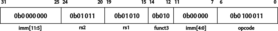
The opcode field with a value 0b0100011 combined with the funct3 field containing value 0b010 form a CPU instruction to store a word-sized value from a register to a memory location specified in other instruction fields. The rs2 field specifies the source register containing the value to be stored. The 0b01011 value defines x11 register holding the counter value. The remaining 3 fields, namely rs1, imm[4:0] and imm[11:5], form the memory address used for the operation. rs1 keeps the number of the register holding base memory address. As x10 register was reserved for this address, the rs1 value is 0b01010. Other two fields are used to form an offset from the base address. The x10 register already has final memory address and offset is not required therefore both these fields have zero values. All these fields combined give 0x00b52023 which is the fourth instruction in the program.
Jump to beginning
The last instruction should make the CPU to jump back to the beginning and create an indefinite cycle. J format instruction is used for this purpose:
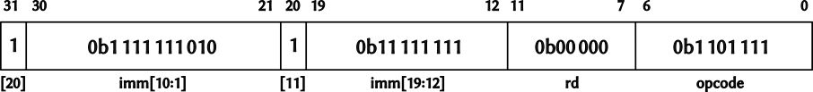
As in all other instruction formats, this one starts with the opcode field and its value is 0b1101111. The rd field is used as a destination register in jump and link operations to store the address of the instruction following the jump. In other words, program counter + 4 value is stored in the destination register. This is not required in my case so the value of this field is 0b00000 which means x0 register and the link address will be effectively discarded. The remaining four fields encode a signed offset from the current program counter value. The jump should be to the loading instruction which is 3 instructions back starting from the jump instruction itself. As compressed instructions are not used, this gives 12 bytes offset value which is encoded in sign extended format and placed in the 4 fields for immediate value. The reason behind splitting immediate value into 4 different fields is to simplify instruction decoder and reduce the cost of simplest hardware3. Pay attention that this time the immediate value starts from its first bit and the zeroth bit is skipped. This is due to the fact that all RISC-V instructions are 32-bits wide or 16-bit wide in case compressed instructions are enabled, so the offset is in multiples of 2 bytes. The final instruction in the hexadecimal format is 0xff5ff06f.
Final program
The final step in preparing the program is to place all composed instructions into an assembly file. Here is the final version of the program:
.align 2
.section .text

.word 0x80000537
.word 0x00052583
.word 0x00158593
.word 0x00b52023
.word 0xff5ff06f
The .section .text directive is used to instruct the assembler to start adding program instructions to the code section. As I am using manually prepared machine instructions instead of actual assembly code, the assembler should be instructed to place raw data into the code section. The .word directive is used for this purpose and it instructs the assembler to put a 32-bit data with the specified value.
The RV32I ISA requires all instructions to be stored on 4-bytes aligned addresses. To ensure this requirement is fulfilled, the .align 2 directive is added to the beginning of the program. This directive checks if the location counter in the program is a multiple of 2 to the power N, where N = 2 is specified as the directive argument, and it advances the counter to the next aligned location in case this requirement is not met.
Let’s compile the program to the target binary format and then disassemble it to make sure it corresponds to the manually assembled instructions:
$ riscv64-unknown-elf-objdump -d build/app.elf

build/app.elf:     file format elf32-littleriscv


Disassembly of section .text:

20400000 <.text>:
20400000:       80000537                lui     a0,0x80000
20400004:       00052583                lw      a1,0(a0) # 80000000
20400008:       00158593                addi    a1,a1,1
2040000c:       00b52023                sw      a1,0(a0)
20400010:       ff5ff06f                j       20400004
        ...
You can find the program and a Makefile for building it in the repository.
Concluding thoughts
The experiment described above looks like a lot of effort for a tiny program. Was it a pure mental exercise or the knowledge gained can be used in practice? I would outline a few areas where it can be useful or even mandatory. Obviously tool chain developers need to know how to assemble machine instructions in order to add support for new hardware platforms. Another example would be reverse engineering where source code may not be available and an existing binary image needs to be modified. There is also a special case of working around hardware bugs. Adding a work-around to a tool chain may not be possible or viable in such cases and manually crafted instructions could be a possible way of fixing it.
-
Refer to a wonderful introduction to RISC-V instruction format by Daniel Magnum. ↩︎
-
RISC-V specification has a more formal description of instruction formats. It also specifies all opcodes used in this post in the RV32/64G Instruction Set Listings chapter. ↩︎ ↩︎
-
See Immediate Encoding Variants chapter in the RISC-V specification for further details about immediate values in the instructions. ↩︎